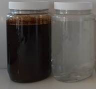
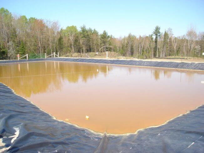
Phenol and its derivatives (phenols, or phenolic compounds) are moderately water-soluble pollutants, common to the wastewaters of various industries, including oil & gas, paint manufacturing, phenolic resin production, paper and pulp factories, and pharmaceutical industries. Phenolic compounds are used in low concentrations in disinfectants, and are also present in many alcoholic beverages, pharmaceuticals, and cosmetics.
Excessive phenolic compounds are harmful to human health and the environment. Chlorophenols, by-products of chlorinating phenol-containing water, are carcinogens.
Existing treatment options include biodegradation, distillation/evaporation, adsorption and extraction, membrane separation, and chemical oxidation. A treatment system needs to be chosen and engineered carefully, with consideration of specific wastewater chemistry, operating conditions, and economics.
Recent advances in membrane separation technology can help optimize the treatment of phenolic compounds-contaminated wastewaters, making zero liquid discharge (ZLD) or minimum liquid discharge (MLD) options more cost-effective.
Phenol (C6H5OH), the simplest member of the phenols family.
Uses, Toxicity, & Wastewater
Phenolic compounds are profoundly toxic to humans, animals, and aquatic life, and can also form carcinogenic chlorophenols in the presence of chlorine. They are considered priority water pollutants by the EPA and the NPRI in the USA and Canada, respectively. Many jurisdictions have strict discharge limits for phenols, typically <0.5 mg/L.
The phenolic compounds consist of an aromatic hydrocarbon group bonded to a hydroxyl group (–OH). Phenols are often moderately water-soluble and smaller phenol molecules can be volatile. Phenols occur naturally in small, relatively harmless concentrations. They are also synthesized on an industrial scale for use in disinfectants, medicinal products, and as ingredients for many polymers, resins, and rubbers for the plywood, tire, construction, automotive, and appliance industries. Small quantities are present in alcoholic beverages, pharmaceuticals, and cosmetics. Phenols can be found in the wastewaters of these industries and others, such as oil & gas.
Phenols face strict discharge limits.
Treatment Options for Phenols in Wastewaters
Many technologies are available for the treatment of phenols-laden wastewaters—with highly varied advantages and disadvantages. For example, some are destructive, while others allow the recovery of phenols for potential reuse. The economics of the different processes vary significantly depending on water chemistry, scale, treatment requirements, and other operating conditions. Options need to be carefully analyzed for a specific application before treatment decisions are made. Many of the available phenol treatment processes are discussed below and summarized in this table.
Treatment
Description
Recovery
Pros
Cons
Bio- Degradation
Uses microorganisms to biodegrade phenols
Destructive
Cost-effective
Safe & easy
Simple, harmless products
Not suitable for high phenols concentration/TDS/acidity, etc.
May require other chemical treatment/aeration, etc.
Large space requirements
Membrane Separation
Uses high pressure & fine membranes to reject phenols, other compounds, & ions
Possible
Cost-effective & reliable
Small footprint, scalable
Produces low volume of concentrated brine
Risks such as fouling & scaling need to be managed
Cannot meet very low discharge requirements, but can be combined with other steps.
Distillation/ Evaporation
Uses heat & difference in volatility to separate phenols from water
Possible
Good for high concentrations
Good potential for recovery & reuse
Costs relatively high
Energy intensity
Adsorption & Extraction
Phenols adsorb to solids such as activated carbon (AC)
Solvent extraction uses relative solubilities to separate liquids
Adsorption: typically
unfeasible
Extraction: possible
AC/solvents cost-effective for low concentrations.
Recovery from solvents possible
Polish to extremely low concentrations
Not economical for high concentrations due to high consumable costs
Requires disposal/recycling of spent AC/solvents
Other organics increase cost
Chemical Oxidation
Uses one of a variety of oxidising methods, e.g. the Fenton reaction
Destructive
Different strategies available
Scalable
Costs can be high for some chemistries
High consumable or energy costs
Products may require further treatment/precipitation/solids management
Biological and Enzymatic Degradation
Biological treatment is a highly established, successful method for the removal of phenols from water. The treatment uses either aerobic or anaerobic microorganisms to biodegrade phenols. It is relatively inexpensive, safe, easy-to-operate, and environmentally friendly. It generally produces simple, harmless products. Membrane bioreactors (MBRs) are a variant of conventional bio-degradation. They use an activated sludge process combined with a membrane filtration step to produce very high-quality water with a small footprint.
Another phenol treatment uses enzymes to catalyze phenol polymerization for precipitation from water. Depending on the circumstances (e.g. availability and cost of appropriate enzymes) it can be even more cost-effective than biological treatments.
However, both biological and enzymatic treatments are not suitable for all water chemistries, for example, high concentrations of phenols, high salinity, and high acidity. These treatments may also require interventions such as further chemical additives and aeration. This means that they are not suitable or cost-effective for all applications.
Biological treatment aeration tanks
Membranes
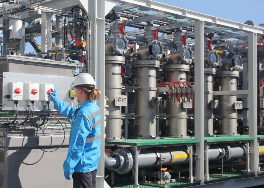
Membrane methods use reverse osmosis (RO) membranes to reject phenols, as well as other compounds and ions. RO membranes are typically cost-effective and reliable, with low power consumption, a small footprint, and scalability. Although they have good rejection performance for many phenols, their performance can be pH dependent. Furthermore, a polishing step may help to further lower the phenol concentration to reach discharge limits, especially for smaller phenol-family molecules. They are particularly suited to treating high concentrations that are unsuitable for biological treatment.
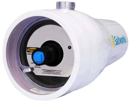
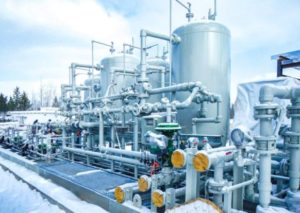
Some risks must be considered such as membrane fouling and scaling. However, comprehensive membrane treatment processes with appropriate pre-treatment can manage the risk effectively, making RO and nanofiltration (NF) very cost-effective and convenient for the treatment of phenols. Saltworks’ XtremeRO system is depicted below.
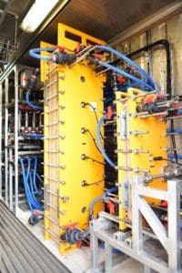
XtremeRO reverse osmosis system
Distillation/Evaporation
A variety of evaporation/distillation options are possible for the separation of phenols from wastewater. They use the relative volatility of some phenols to purify water. Distillation methods generally have high energy costs and are typically viable for high phenol concentrations only. Due to the spread of volatility across different members of the phenol-family, such methods may not be suitable for all phenols.
Pervaporation (PV) applies a vapor pressure difference to pull phenol vapor through a membrane, exploiting the difference between the affinities of phenol and water to the membrane. With relatively low energy consumption and simple operation, it is effective for separating low volatility organics, including some phenols.
SaltMaker MultiEffect evaporator
Adsorption and Extraction
Adsorption is commonly used to remove phenols, using solid consumables such as activated carbon (AC). The economics depend on the cost of the adsorbent and the cost of its disposal or recycling. Once spent, the management of phenol-saturated solids is critical and includes options for reuse or disposal. Although usable for the treatment of any concentration of phenols, adsorption is most cost-effective for removing low concentrations, making it an excellent final-step polish. The presence of other organics in the water will increase the cost since these may also occupy adsorption sites in the AC.
Solvent extraction is a similar, liquid-liquid process. It is standardized and non-destructive for phenols compounds, useable over a wide range of concentrations. However, it is only cost-effective in some circumstances, typically on a small scale.
Activated carbon
Oxidation and Fenton’s Reaction
Oxidation is a destructive method for the treatment of phenols and other organics. It can use a variety of conventional oxidizing agents (ozone, chlorine, permanganate, etc.), catalysts, and conditions, including irradiation. The choice of oxidation strategy depends heavily on the economics, wastewater chemistry, and other conditions. Costs are typically low to moderate, and oxidation can be used in varied operating conditions. Reaction products may require further treatment or be precipitated (meaning that consideration may need to be given to appropriate solids management).
The Fenton reaction (and variants) use H2O2 and Fe2+ to produce hydroxyl radicals, which oxidize organics such as phenols. As a phenol treatment method, it is usually cost-effective, and suitable for high concentrations. However, it is pH dependent and may not suit all water chemistries. As with many other chemical treatments, sludge is produced that requires management.
Contact Saltworks for Phenols Solutions
Saltworks’ process experts support our clients by providing options analysis—we help you to decide on the right treatment for your phenols-laden wastewater. Providing you with the right solution is what matters most, so our recommendations may include solutions from third-party vendors rather than our own products (or combinations of both). We have extensive experience in developing specifications for third-party vendors for our clients. Given our position in the water industry, we know who builds the best sub-processes and process elements.
Saltworks offers two ‘in-house’ solutions for phenols that are adaptable for new or existing treatment chains:
Option 1 uses reverse osmosis/nanofiltration, combined with our ultra-high pressure XtremeRO system to remove most of the phenolic compounds. We optionally add polishing to remove the rest cost-effectively. Option 1 is better suited for low-TDS wastewater.
Option 2 uses our SaltMaker evaporator crystallizers to reduce the volume of high-TDS wastewater to minimal or zero liquid discharge. Post-treatment systems can polish the phenol-containing condensate. Option 2 is better suited for high-TDS wastewater.
Once a treatment technology is chosen, we can bring our testing, automation, and piloting expertise to the project. Get in touch to see how Saltworks can help you to meet your phenols challenges.
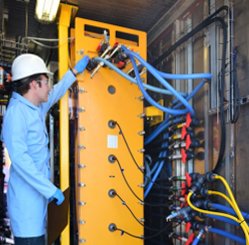
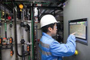
Saltworks engineers operating a pilot plant
About Saltworks
Saltworks Technologies is a leader in the development and delivery of solutions for industrial wastewater treatment and lithium refining. By working with customers to understand their unique challenges and focusing on continuous innovation, Saltworks’ solutions provide best-in-class performance and reliability. From its headquarters in Richmond, BC, Canada, Saltworks’ team designs, builds, and operates full-scale plants, and offers comprehensive onsite and offsite testing services with its fleet of mobile pilots.
Saltworks is pleased to announce that recent advancements in reverse osmosis technology are now commercially available. Reduce conventional RO brine volumes by 50%, achieving brine concentrations of 130,000 to 150,000 mg/L TDS with spiral wound RO membranes.
Reverse osmosis (RO) is the best available technology to treat landfill leachate for surface discharge. Possible trace volatile organic compounds (VOCs) and ammonia emerging in the RO permeate can be removed with a polishing step to meet the highest discharge standards.
No two pharmaceutical wastewaters are the same. Saltworks can help you to treat complex wastewaters from this critical industry with certainty. We implement solutions that target organics, metals, and ions for removal, reduce brine waste, and allow water reuse.
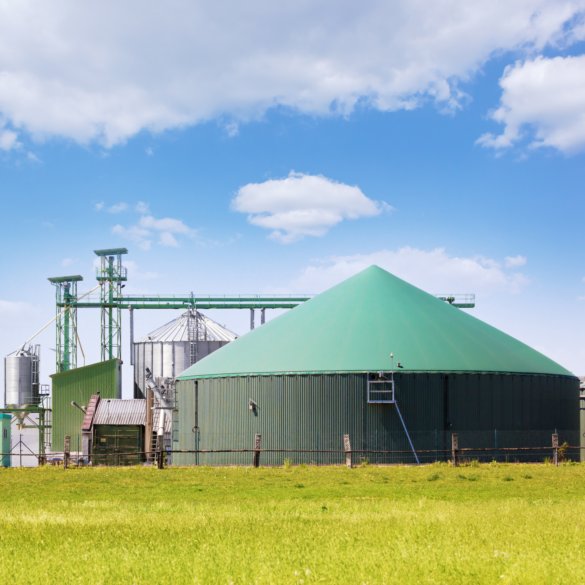
Digester wastewaters are by-products of biogas production in anaerobic digesters. They require treatment prior to disposal. To meet regulation compliance, treatment options range from minor interventions such as selective contaminant removal, to major interventions such as minimum and zero liquid discharge (MLD/ZLD).
Ultrafiltration (UF) is widely used in water treatment to filter out particles within a size range of about 0.01 to 1 µm, e.g. suspended solids, bacteria, viruses, oils and grease.
The vast majority of UF systems employ polymeric membranes, especially in municipal water treatment. However, polymeric UF membranes are restricted in their field of application. Polymeric membranes are less reliable in harsh chemical environments, with slurries that can plug the membrane elements, and when performing oil & grease removal.
Ceramic ultrafiltration membranes open the UF application range to the above severe conditions and provide a polymeric ultrafiltration alternative for the treatment of highly turbid water. However, they have historically been viewed as expensive.
Recently ceramic membranes have become more widely available at lower costs. In addition, companies such as Saltworks have developed robust process and control systems to keep the ceramic membranes clean. This opens opportunities to employ ceramic UF to filter highly impaired waters where polymeric UF cannot cope.
This article introduces a new type of ceramic membrane system and explains how it opens the application range. An example of treatment of oil and grease in produced water is provided.
XtremeUF: An ultrafiltration solution for highly impaired industrial waters
What Do I Need to Know About Ultrafiltration?
Ultrafiltration (UF) uses a pressurized membrane to achieve TSS (total suspended solids) removal in wastewater within a size exclusion range of about 0.01 to 1 µm. This is a critical regime for the screening of particulate, bacteria, viruses, oils and grease. UF is therefore an essential step for many processes, including municipal wastewater treatment and pre-treatment for reverse osmosis.
Polymeric and Ceramic Membranes
The majority of UF membrane installations are polymeric, which imposes some critical technical limits. Operation at high temperatures, exposure to high/low pH, high TSS concentration, or oils and grease may restrict the longevity and performance of polymeric membranes or make them unsuitable altogether. A typical polymeric membrane module consists of thin hollow fibres (imagine a handful of hollowed-out spaghetti) with flow channels that are 0.2–3 mm in diameter. Failure of polymeric ultrafiltration membranes occurs when these fibres are damaged or blocked, which is especially likely in severe applications.
Ceramic UF membranes are an ultrafiltration solution in the treatment of a wide range of highly impaired wastewaters, such as highly turbid waters, oil & gas produced waters, or slurries. The usage of ceramic membranes has historically been restricted to especially challenging conditions, largely on the grounds of cost. Recent advances in ceramic membrane manufacturing and availability mean that they are now a commodity item, widely available at a lower cost than in the past. For challenging waters, ceramic membranes can now be a much more viable economic choice.
A typical ceramic membrane is composed of a sintered material such as alumina or zirconia (imagine a porous, hard rock that can take a real beating). Unlike polymeric materials, ceramics are stable at high temperatures, will not swell and deform in the presence of oil and grease, and can repeatedly withstand harsh chemical cleans. In addition, commodity ceramic membranes are extruded with flow channel openings of 2–8 mm in diameter, making them less susceptible to blockage in high TSS applications. A ceramic membrane is highly robust and—with the correct automated processes—can recover from performance degradation to maintain operations.
Polymeric (left) and ceramic (right) membranes
Keeping Ceramic Membranes Clean
To keep ceramic membranes operating at their best, it is important to employ a combination of automated-cleaning methods. The first defense is to achieve high crossflow, minimizing the stagnant zone or boundary layer near the membrane surface. Higher crossflow, or velocity at the membrane surface, will wash particulate away. There are two crossflow velocities: operational and forward flush—whereby velocity is dramatically increased for a short duration by 2-3× to wash away debris. This can require very high flow rates and energy consumption.
Saltworks has developed a novel hydraulic system that minimizes energy consumption and back pressure while maximizing velocity at the membrane surface. Our forward flushes are done in a smart way, to increase the crossflow to wash away any particulate while minimizing the operational impact on the system.
Backwashing is another cleaning method that incorporates hydraulic pressure to push particulate off the membrane surface. Chemical cleaning is comparatively expensive and used less frequently. Nevertheless, we build in and automate all of these systems.
Saltworks’ automated XtremeUF system performs cleaning in an intelligent and responsive manner, based on continuous online monitoring of membrane performance. The system selects from multiple levels of cleaning cycles to enable the membrane to maintain flux without irreversibly fouling. We clean only when and how it is necessary. This maintains performance and uptime while minimizing energy consumption.
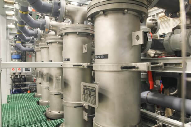
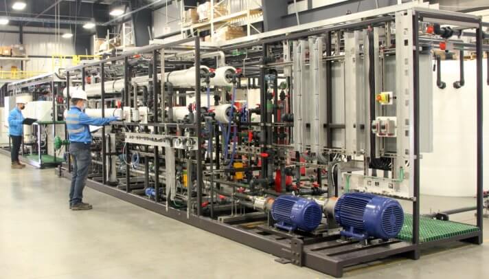
Our skidded XtremeUF ceramic ultrafiltration system
Flux
UF performance is quantified by a measure of filtrate flux: a normalized unit that represents the filtrate flow rate per unit area of membrane. The two most common flux units are LMH (L/m2/h) and GFD (gallons/ft2/day). A typical polymeric membrane will operate in the range of 40–80 LMH (24–47 GFD). A ceramic membrane will operate in the range of 50–1000 LMH (29–588 GFD). Pinpointing where an application will fall on this spectrum is a function of particle size, oil/organics type, concentrations and operating pressure. Lower flux applications will require more membrane area and more energy to meet the same nominal filtrate flow rate. Using experimental data, Saltworks has developed a performance map of expected flux ranges for different industries.
XtremeUF flux ranges for a selection of waters from different industries
The Origins of XtremeUF
Saltworks focuses on treating the toughest waters. We identified a gap for XtremeUF on the basis of three observations: significant demand for treating waters that are too challenging for polymeric UF; reduction in ceramic membrane prices; and an opportunity to apply our know-how to implement intelligent automation in cleaning. To produce an XtremeUF system, we package commodity ceramic UF membranes into well-engineered and intelligently automated systems that can take slurry concentrations to new levels.
We needed XtremeUF to meet the following criteria:
Removal of suspended solids and organics from the most challenging slurries and impacted wastewaters
Concentration and thickening of slurries
Performance maintenance through our proprietary process of intelligently automated cleaning
High tolerance to a wide range of waters and conditions, i.e. turbidity, oils, grease, chemicals, pH and temperature
Corrosion resistance appropriate for high total dissolved solids (TDS) water
XtremeUF feed and filtrate: EOR produced water (left) and filtrate (right)
Choosing the Right Materials for You
The choice of construction materials of pipework and pumps is critically important for the performance and longevity of UF systems. For high chloride waters, corrosion-resistant materials are required. Saltworks selects and incorporates the correct materials for your application. This may include Stainless Steel 316L, Super Duplex Stainless Steel, 6 Moly Alloy, Titanium or even non-metallics such as CPVC. For short-lived or cost-sensitive projects, this may include an economic trade-off to accept some corrosion, especially with known replacements.
One of our XtremeUF testing and piloting systems
What Differentiates XtremeUF from Other UF Processes?
Robust and suitable for a very wide range of applications and operating conditions, Saltworks’ XtremeUF removes suspended solids and organics from the most challenging slurries and impaired wastewaters. XtremeUF can concentrate slurries to up to 10% TSS (100,000 mg/L) with a high tolerance to turbidity, oils, grease, chemicals, pH and temperature.
Using our intelligently automated self-cleaning controls, XtremeUF cleans itself as it operates, maintaining flux with minimum power consumption and operator intervention. We can treat wastewaters that no one else will touch.
Use of commoditized, widely available ceramic membranes enables a wide selection of vendors in the future.
Versatile and adaptable, XtremeUF can be constructed with a variety of corrosion-resistant materials for use with high salinity, or other corrosive water. We offer filtration specifications of 0.01, 0.05, 0.1, 0.5, and 1.2 µm.
XtremeUF pilot at an enhanced oil recovery site
Example Application: Preventing Reservoir Plugging in Enhanced Oil Recovery
Enhanced oil recovery (EOR) maximizes reservoir production by injecting water to push out more oil. While reinjecting the water may be desirable, the water becomes saline and picks up particulate during the process. The water may also have been treated with polymers to increase its viscosity, to push out even more oil.
This is a prime example of where traditional polymeric UF membranes do not fit, while ceramic membranes do. XtremeUF can produce clean filtrate—removing oils, grease, polymers and particulate—from produced water. This allows the injection/reinjection of high-quality water into a reservoir undergoing enhanced oil recovery, reducing the potential for reservoir plugging. It can also facilitate the ocean discharge of produced water, by removing all of the above prior to discharge.
Here, you can read about a pilot test where an XtremeUF system was dispatched to a live oil field in an EOR scenario, and its reliable operations were successfully demonstrated.
How Can We Help?
Can XtremeUF help you to meet your targets? Is ceramic or polymeric filtration right for you? Our Saltworks experts are ready to test your water to establish feasibility and indicate site performance. Contact us to learn more.
You can also see our spec sheet to see where polymeric membranes stop and ceramic UF membranes start.
About Saltworks
Saltworks Technologies is a leader in the development and delivery of solutions for industrial wastewater treatment and lithium refining. By working with customers to understand their unique challenges and focusing on continuous innovation, Saltworks’ solutions provide best-in-class performance and reliability. From its headquarters in Richmond, BC, Canada, Saltworks’ team designs, builds, and operates full-scale plants, and offers comprehensive onsite and offsite testing services with its fleet of mobile pilots.
Digester wastewaters are by-products of biogas production in anaerobic digesters. They require treatment prior to disposal. To meet regulation compliance, treatment options range from minor interventions such as selective contaminant removal, to major interventions such as minimum and zero liquid discharge (MLD/ZLD).
With the growing importance of brine management, modernized chemical softening systems can enable economic ultra-high recovery reverse osmosis, minimizing RO brine volume, disposal costs, and reliability risks.
The many options for managing brine, a term for saline wastewater from industrial processes, fall under two categories: brine treatment and brine disposal. Brine treatment involves desalinating the brine for reuse and producing a concentrated brine (lower liquid waste volume), or residual solids (zero liquid discharge).
Saltworks Technologies Inc. (Saltworks) completed a pilot on cooling tower blowdown demonstrating minimal liquid discharge (MLD) with up to 70x volume reduction using advanced membrane systems. The MLD paper presents brine management results and economics for water plant designers. Readers will learn how to concentrate brines to 130,000 mg/L total dissolved solids (TDS) with reverse osmosis membrane technology while avoiding scaling and fouling. The work is intended to inform widening use of membrane-based brine concentration systems in order to offset more expensive evaporation or disposal methods.
Pilot test results are presented for cooling tower blowdown brine at 1,800 mg/L TDS. The pilot test consisted of several methods, used to achieve multiple volume reduction factors (recovery): 5X (80%), 10X (90%), 20X (95%), 40X (97.5%), and 70X (99%). Each jump in volume reduction adds plant complexity and cost. Each step will be explained and mapped so readers can learn about the technology and investment required to take the next step in recovery improvements.
The plant consisted of a robotized chemical softening system, BrineRefine, designed for use with variable water chemistry. This system includes a real time calcium sensor and precipitation management system. The plant also consists of ultra high-pressure reverse osmosis, XtremeRO, with spiral wound membranes rated for 1,800 psi (120 bar) to achieve ultra high recoveries.
Saltworks Technologies is a leader in the development and delivery of solutions for industrial wastewater treatment and lithium refining. By working with customers to understand their unique challenges and focusing on continuous innovation, Saltworks’ solutions provide best-in-class performance and reliability. From its headquarters in Richmond, BC, Canada, Saltworks’ team designs, builds, and operates full-scale plants, and offers comprehensive onsite and offsite testing services with its fleet of mobile pilots.
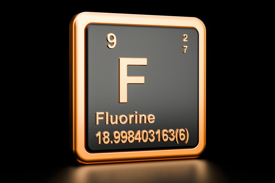
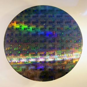
Production of semiconductors and microelectronics generates wastewater with elevated levels of fluoride, often requiring treatment before discharge.
Fluoride removal is practiced in drinking water via adsorption, ion-exchange and/or reverse osmosis. These technologies should also be considered for industrial wastewater treatment, but are generally a better fit for low concentrations of fluoride.
Calcium fluoride precipitation and coagulation is another option to remove fluoride from industrial wastewater to meet discharge requirements. This is suited for the much higher fluoride concentrations typically associated with the semiconductor industry.
New modular, intelligent, and automated chemical precipitation with a ceramic membrane filtration system eliminates the challenges of chemical overdosing and large footprint requirements.
Fluoride Treatment Options
In the microelectronics industry, fluoride wastewaters are generated during hydrofluoric acid etching of semiconductors. Hydroflouric acid is also employed in the solar cell and metal-plating industries. Typical concentrations of fluoride in these wastewaters can range from 100 mg/L to more than 10,000 mg/L. In general, fluoride discharge limits are less than 20 mg/L if the wastewater can be discharged into a public sewer system, and less than 5 mg/L if the wastewater is discharged into an aquatic environment. In some jurisdictions, the fluoride discharge limit can be less than 2 mg/L. It is noted that some municipalities add fluoride to drinking water (0.5–1.5 mg/L) because of its beneficial prevention of dental cavities. However, excessive fluoride is harmful to human health causing skeletal fluorosis (bone disease).
Existing removal options for fluoride wastewaters include: 1) calcium fluoride (CaF2) precipitation and coagulation, 2) adsorption, 3) ion-exchange, and 4) membrane-based processes such as reverse osmosis and electrodialysis. An industrial wastewater with a high fluoride concentration is often treated through the CaF2 precipitation and coagulation method. Adsorption, ion-exchange, and reverse osmosis are more often used in drinking water applications and for final fluoride polishing.
An overview of the pros and cons for these fluoride removal options are summarized in Table 1.
Table 1. Comparison of Fluoride Removal Technologies
Technology
Pros
Cons
CaF2 Precipitation & Coagulation (Conventional)
• A commonly practiced method through using lime (Ca(OH)2) and/or calcium chloride (CaCl2) to precipitate calcium fluoride
(CaF2) down to its solubility limit. This is followed by aluminum based coagulation to further reduce fluoride to meet low discharge limits.
• Removes other contaminants such as acid, silica, and heavy metals (cadmium, copper, chromium, lead, mercury, and zinc).
• Two separate reaction processes with long hydraulic retention times.
• CaF2 and Al(OH)3 precipitates result in fine particles that take long times to settle, requiring large sedimentation and clarification tanks.
• Overdosing of lime and coagulation agents, resulting in high chemical costs and excess wet sludge.
Adsorption & Ion-exchange
• High availability of adsorbent options, such as activated alumina, modified activated carbon, hydroxyapatite, zeolites, char, and fluoride specific ion exchange resin.
• Reduces fluoride to 1 mg/L.
• Best fit for removal of low concentrations of fluoride.
• Not cost-effective for industrial wastewater with high fluoride concentration due to high consumption of the adsorbent and/or high cost to regenerate ion exchange resins.
• Operation pH limited between 5 and 8. Other anions (e.g., chloride, nitrate, sulfate) present in the wastewater reduces fluoride removal efficiencies.
• An ion exchange regeneration wastewater brine requires management.
Reverse Osmosis & Electrodialysis
• Reduce fluoride to 1 mg/L.
• Remove other contaminants including total dissolved solids.
• Minimal chemical consumption.
• More compact footprint and greater automation over other options.
• A good polishing method if required.
• Membranes are not compatible with hydrofluoric acid or fluorosilicic acid in the wastewater.
• Possible membrane fouling by other inorganics and organics in the wastewater.
• Pretreatment often required.
• A concentrated brine reject is produced requiring management.
During CaF2 precipitation, lime is used to neutralize any waste acids in the fluoride wastewaters. With fluoride concentrations less than 1,000 mg/L, lime is often selected as the sole calcium source to precipitate fluoride. Lime has a low solubility at 0.18% by weight so for wastewater with high fluoride concentrations it used together with calcium chloride, which has a high solubility. Excessive lime addition often results in undesired consumption of aluminum coagulants in the downstream coagulation step and increases sludge quantities.
Calcium fluoride precipitation can reduce the fluoride concentration down to about 8–20 mg/L, depending on the total dissolved solids concentration in the wastewater. A second coagulation step, using aluminum-based coagulation agents, is required to further reduce fluoride to less than 5 mg/L.
The calcium fluoride precipitation and coagulation method, however, has two disadvantages: 1) CaF2 from the precipitation step and Al(OH)3 from the coagulation step are both very fine particles, so their sedimentation and clarification times are very long, requiring large footprint clarifiers; and 2) overdosing of lime and coagulation reagents results in a higher chemical cost and a large volume of wet sludge for final dewatering treatment.
Recent technology and process improvements in chemical precipitation and filtration can address both disadvantages associated with calcium fluoride precipitation and coagulation.
Fluoride Treatment Using Advanced Chemical Precipitation and Filtration
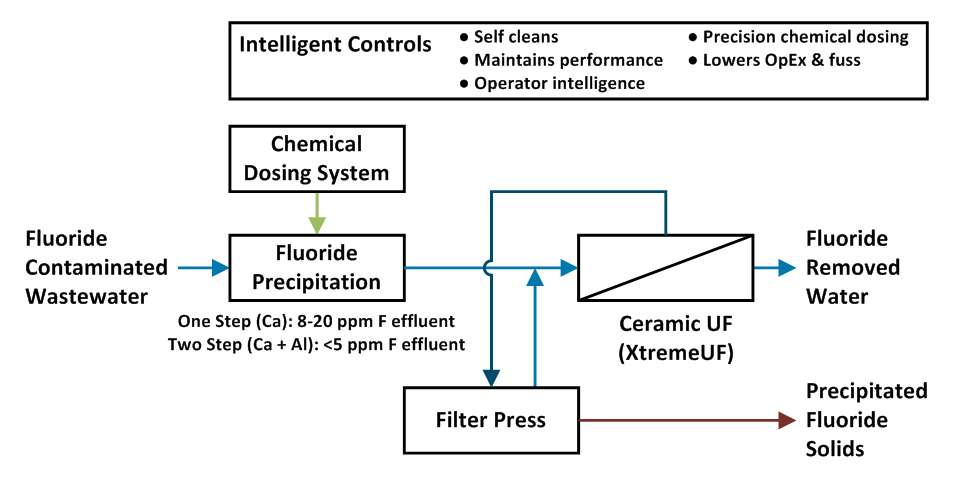
Saltworks developed a cost-optimized solution for fluoride removal using our BrineRefine advanced chemical precipitation and XtremeUF ceramic ultrafiltration systems. An example process flow diagram is presented in the figure below. The combination of BrineRefine and XtremeUF in calcium fluoride precipitation and coagulation eliminates the need for large clarification/sedimentation tanks and multimedia filtration and/or cartridge filtration, reducing footprint, maintenance and operating costs.
Process flow diagram showing fluoride treatment using an advanced chemical precipitation and filtration process
BrineRefine is an improvement to existing chemical precipitation for fluoride removal. BrineRefine uses intelligent controls for automated precise dosing, avoiding lime and calcium chloride under/over-dosing to precipitate CaF2. XtremeUF is an ultra-robust ceramic ultrafiltration system that self-cleans while it operates. XtremeUF filters the CaF2 and Al(OH)3 fine particles from the coagulation process, leaving a clean water filtrate that could be discharged or reused directly in hydrofluoric acid etching of semiconductors. BrineRefine and XtremeUF are fully integrated into a single smart and automated plant.
Contact Saltworks for a detailed review of your fluoride wastewater treatment project.
About Saltworks
Saltworks Technologies is a leader in the development and delivery of solutions for industrial wastewater treatment and lithium refining. By working with customers to understand their unique challenges and focusing on continuous innovation, Saltworks’ solutions provide best-in-class performance and reliability. From its headquarters in Richmond, BC, Canada, Saltworks’ team designs, builds, and operates full-scale plants, and offers comprehensive onsite and offsite testing services with its fleet of mobile pilots.
This article introduces a new type of ceramic membrane system and explains how it opens the application range. An example of treatment of oil and grease in produced water is provided.
Heavy industry, manufacturing, and natural resource-based industries often use large volumes of water and generate wastewaters requiring treatment. Saltworks designs, builds, and operates advanced wastewater treatment plants that economically and reliably treat tough industrial wastewaters.
The manufacturing of microelectronics generates unique wastewaters. Saltworks can help you to manage wastewater flows from microelectronics production, targeting fluoride, ammonia, metals, and ions, reducing brine waste, and allowing water reuse.
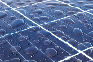
Solar PVs manufacturing facilities produce industrial wastewater streams with complex chemistries, which must be managed for reuse, discharge, or disposal. Constituents of concern include fluoride, organics, metals, suspended solids, acids, alkalis, and others.
Reverse osmosis (RO) is the best available technology to treat landfill leachate for surface discharge. Possible trace volatile organic compounds (VOCs) and ammonia emerging in the RO permeate can be removed with a polishing step to meet the highest discharge standards.
Membrane fouling and RO leachate brine volume management need to be considered up front, and will influence treatment costs.
A robust and fouling resistant ceramic ultrafiltration module can pretreat the foulants in landfill leachate to make existing spiral wound RO more reliable.
RO leachate brine volume can be minimized through a membrane brine concentrator: ultra-high-pressure reverse osmosis in conjunction with advanced scaling-removal chemical softening. It can concentrate leachate total dissolved solids (TDS) up to 140,000 mg/L – around 10X volume reduction for the raw leachate depending on its water chemistry.
Current State of Reverse Osmosis for Landfill Leachate
Landfill leachate is a foul-smelling wastewater generated when water trickles down through buried solid wastes. Landfill leachate contains a wide range of pollutants, such as ammonia, heavy metals, organic matter, personal care and pharmaceutical chemicals, pesticides, per- and polyfluorinated substances (PFAS), total dissolved solids (TDS), and many more. In many jurisdictions, landfill leachate is prohibited from discharge into a public sewer without treatment. However, landfill leachate can be treated to meet regulation guidelines for safe discharge into an aquatic environment.
Existing landfill leachate treatment generally integrates the following options:
physical-chemical (phys/chem) treatment using adsorption, air-stripping, flotation, coagulation/flocculation, chemical precipitation, membrane separation (ultrafiltration, nanofiltration, and reverse osmosis), and advanced oxidation;
biological treatment method using anaerobic, aerobic and anammox treatments; and
evaporation using mechanical vapor recompression and submerged combustion evaporation.
When landfill leachate must be treated to meet surface water discharge quality, reverse osmosis (RO) is the best available technology. RO offers an absolute separation barrier for all pollutants, more compact footprint and greater automation over other options. A final polishing step after RO can remove any trace volatile organic compounds (VOCs) and ammonia that may slip through the RO membrane into the permeate.
RO however also has two disadvantages for landfill leachate: membrane fouling and high disposal cost for a large volume of RO leachate brine. RO with unique modules such as disc-tube RO (DTRO) has claimed to address the membrane fouling issue to a certain degree. DTRO equips larger feed channels than existing spiral wound RO. During operation, landfill leachate is recirculated in DTRO module under high turbulence and crossflow to clean membrane surface. However, active membrane area of DTRO is much smaller than that of a spiral wound RO. DTRO requires a big footprint and high energy consumption with excessive brine recirculation. Operators also allege that DTRO require frequent cleaning maintenance and internal rebuilds. DTRO has not addressed the RO brine issue. The RO brine is usually about 20 – 40% by volume of the original leachate depending on the leachate chemistry. RO leachate brine is oftentimes disposed by evaporation, incineration, advanced oxidation, and/or solidification/stabilization, which are energy intensive and with high cost.
Recent technology and process breakthroughs in desalination can help address both RO disadvantages while treating landfill leachate. There are several emerging commercial versions of ceramic membrane modules (for example, XtremeUF) that enable foulant removal pretreatment and the use of commoditized spiral wound RO for wastewaters with heavy foulants (for example, produced water from oil/gas production). Ceramic membranes are long-lasting, fouling-tolerant, and easy to clean. After many competitive suppliers entered the ceramic membrane market, membrane costs lowered tremendously over the years. As for RO brine volume reduction, a membrane concentrator, which uses a process of ultra-high-pressure RO (for example, XtremeRO) in conjunction with scaling-removal chemical softening (for example, BrineRefine), can now further concentrate RO brine up to a TDS of 140,000 mg/L, around double the upper TDS limit of existing spiral wound RO.
Saltworks developed a more cost-effective solution for landfill leachate. The solution integrates three recent breakthrough water treatment technologies with four existing options: phys/chem treatment, XtremeUF, membrane bioreactor (MBR), Seawater RO (SWRO), BrineRefine, XtremeRO, and evaporation. Each step addresses a specific pollutant in landfill leachate to deliver an optimized treatment train. The process flow diagram presented in Figure 1 shows all steps to provide a comprehensive view to the reader. Some steps are optional, depending on specific project requirements.
Saltworks engineers can review specific projects to deliver the balance of a simple but cost-effective treatment train.
Ultra-High-Pressure RO for Landfill Leachate
Process flow diagram showing comprehensive treatment steps for landfill leachate.
The phys/chem treatment, if required, precipitates heavy metals that are toxic or inhibitory to microorganisms in the downstream MBR. Some fouling organics (for example, natural organic matters (NOM)) and scaling inorganics (for example, calcium carbonate) are also partially precipitated out.
XtremeUF is an ultra-robust ceramic based ultrafiltration module. It removes the solid slurries from the phys/chem precipitation and most organic foulants (NOM, oil and grease) that will otherwise foul downstream MBR and RO. XtremeUF is built with a well-engineered and intelligently automated package that cleans itself during operation. XtremeUF provides a pretreated “clean” landfill leachate for downstream treatment.
Membrane bioreactor (MBR) biologically degrades ammonia and biochemical oxygen demand (BOD) based pollutants. The MBR is divided into two reaction zones in series: a smaller anoxic zone for nitrogen removal, and a larger aerobic zone where the pretreated leachate is oxygenated for BOD removal. If ammonia removal is not required, the MBR is optional. As the reader can see, every case is unique and may only need a simple treatment train.
Seawater RO (SWRO) operates at less than 1200 psi to first remove dissolved solids, and non-volatile and non-degradable organics in the leachate after MBR. SWRO produces a brine about 20-40% by volume of the raw leachate as well as a treated water. The treated water may require an additional polishing step for trace ammonia and/or VOCs. This added polishing step is nominal in cost; Saltworks has successfully applied it in several projects to meet the highest discharge standards, including offering onsite pilots that result in successful full-scale projects.
BrineRefine removes potential scaling components in the SWRO brine for the downstream ultra-high-pressure RO. BrineRefine is an improvement to existing chemical softening: it helps avoid using coagulants that foul downstream RO systems, and incorporates a simple solid management system that reduces the sludge volume, and improves sludge settling and dewaterability.
XtremeROis an ultra high pressure RO that operates at up to 1800 psi and is designed with widely available ultra-high-pressure RO spiral wound membrane modules. XtremeRO concentrates the BrineRefine treated brine to approximately 140,000 mg/L TDS. Compared to any existing thermal evaporation method, XtremeRO is about 3 times more energy efficient. The volume of landfill leachate brine after the Xtreme Reverse Osmosis is about 10% of the raw leachate volume, enabling a significant downsizing of final brine treatment which could include recirculation back to the landfill, solidification with fly ash or cement, or a final leachate evaporation by an evaporator/crystallizer.
Feel free to contact Saltworks for a detailed review of your landfill leachate project, including risks and opportunities, as well as options to manage the resulting brine residuals.
About Saltworks
Saltworks Technologies is a leader in the development and delivery of solutions for industrial wastewater treatment and lithium refining. By working with customers to understand their unique challenges and focusing on continuous innovation, Saltworks’ solutions provide best-in-class performance and reliability. From its headquarters in Richmond, BC, Canada, Saltworks’ team designs, builds, and operates full-scale plants, and offers comprehensive onsite and offsite testing services with its fleet of mobile pilots.
Saltworks can help you to address your leachate challenges with ultra-high recovery solutions for sewer or surface discharge. We have you covered for chemical, membrane and thermal solutions, including integration when required. Our solutions can reduce your leachate treatment costs, stakeholder risks, and residual waste volumes to manage.
The many options for managing brine, a term for saline wastewater from industrial processes, fall under two categories: brine treatment and brine disposal. Brine treatment involves desalinating the brine for reuse and producing a concentrated brine (lower liquid waste volume), or residual solids (zero liquid discharge).
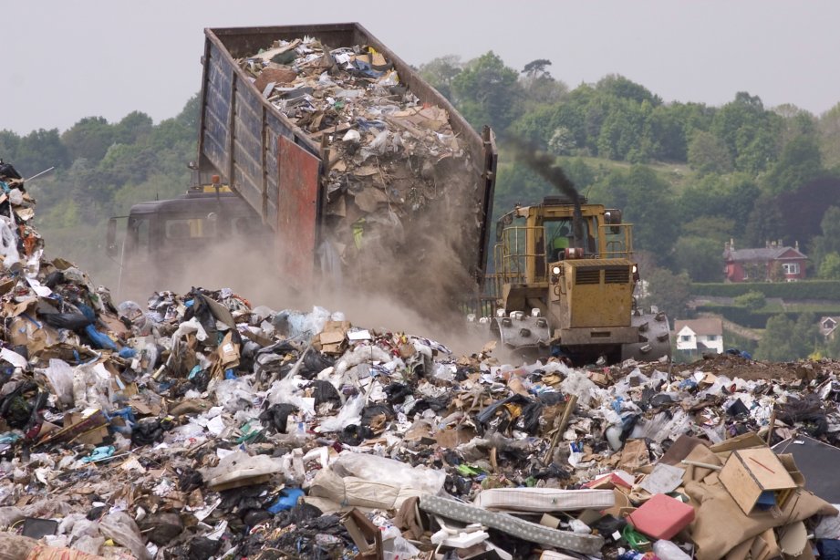
Coal ash pond water may require treatment as leached pollutants from ash pond water pose human health and ecological risks.
Each ash pond water has unique water chemistry and requires an integration of multiple treatment solutions. Treatment methods for the most common pollutants of concern in coal ash pond waters are discussed.
Consider membrane concentrators, minimal liquid discharge (MLD), and zero liquid discharge (ZLD) technologies to reduce brine volumes from treating leachable pollutants.
Process Flow Diagram by USEPA
Treatment Solutions for Coal Ash Pond Waters
The combustion of coal in thermal power plants generates large volumes of coal combustion residuals (CCR), such as fly ash, bottom ash, boiler slag, and flue gas desulfurization (FGD) materials. These CCR are collectively referred to as coal ash. For decades, coal ash has been managed by using river or lake water to sluice it into a large surface water impoundment (also called “coal ash pond”) for its final settlement. Coal ash contains substances such as arsenic, boron, selenium, and heavy metals (cadmium, copper, chromium, lead, mercury, among others). As a result, coal ash pond water, if released into the environment through embankment breaches and seepage of the water through the pond bottom as leachate, may contaminate soil, rivers, lakes, and groundwater. Several U.S. power plants are currently required by regulators to clean up their coal ash ponds and to treat coal ash pond waters as quickly as possible.
Rather, a plant should be designed to meet the treatment objectives and be cost-optimized for the project. This will involve an integration of multiple treatment methods. We hereby provide a “tool box” of treatment methods for the most common pollutants of concern in coal ash pond waters.
Arsenic: Arsenic may exist in coal ash pond waters as inorganic arsenite As(III), arsenate As(V) or organic methylated arsenic compounds. The species of arsenic present in the water will determine the treatment method. Three options for removing inorganic arsenite and arsenate are available:
physical-chemical (phys/chem) precipitation using lime-softening and/or aluminum or iron coagulation;
physical adsorption using ion exchange (IX) resins, activated alumina, green sand or zero-valent iron-based adsorbents; and
reverse osmosis (RO).
The phys/chem precipitation method is often preferred beause it can reduce arsenate down to 0.01 mg/L. When arsenite is the predominant species in the water, an oxidation step is required to convert arsenite into arsenate prior to the phys/chem precipitation process.
Reverse osmosis has the benefit of being able to remove both inorganic and organic arsenic. Phys/chem precipitation or physical adsorption is not effective for organic methylated arsenic compounds. Although work is being done on advanced oxidation processes to target only organic arsenic removal (for example, Fenton oxidation), these are not yet commercial and may be expensive.
Boron: Two options for boron-removal are commonly used:
ion exchange (IX) using boron-selective resin that can reduce boron concentrations to less than 0.1 mg/L, with the spent resins requiring regeneration with acid and base; and
reverse osmosis (RO) under a basic condition (pH > 10), where a polish step for the treated water may be required to reduce boron to < 0.5 mg/L (a compliance level regulated by some jurisdictions).
The polish step could be IX or a secondary RO. At an acidic condition (pH < 7), boron exists as boric acid, which is too small in radius to be rejected by an RO; boric acid will pass through RO membranes into the treated water.
Selenium: Selenium may exist in coal ash pond waters as selenite Se(IV) or selenate Se(VI). Selenite is more reactive and easier to remove than selenate. Phys/chem precipitation using ferrous or ferric reagents is effective in removing selenite but not selenate. Existing selenate removal processes are based on converting selenate into elemental selenium through biological reduction. Although electrochemical reduction processes have been studied to remove selenate, they are not yet commercialized and generate a large volume of solid waste that requires disposal. Reverse osmosis will remove both selenite and selenate, although management of the reverse osmosis brine needs to be considered. In some cases, the brine can be returned to the coal ash pond; however, this will increase the pond salt contents over time.
Heavy metals: Heavy metals (cadmium, copper, chromium, lead, mercury, and zinc) are generally removed by phys/chem precipitation as metal oxides or metal hydroxides. The phys/chem process may not meet stringent discharge requirements, depending on the specific metal and its precipitate solubility. To further reduce heavy metal concentrations after the phys/chem process, a polishing step with reverse osmosis or scavenging agents that react and bind with metals may be required. Most metal scavenging agents are toxic, so care must be taken to ensure that they do not end up in the treated water.
Practical Guidance and Considerations
Each project for treating coal ash pond water will have its own unique water chemistry and required treatment goals. Additional constituents of concern that were not described above, such as total suspended solids and total dissolved solids, may require removal. An experienced wastewater treatment team can engineer and price a solution, which includes an initial desktop study of how to treat the coal ash pond water to meet project objectives and identify risks.
An exemplary, end-to-end treatment train is presented below for the removal of pollutants of organics, inorganics and suspended solids. Not all process steps are needed, depending on the specific project requirements, but are included to demonstrate integration of multiple technologies to meet stringent treatment objectives and end-of-life for residuals.
High-level process flow diagram showing the treatment of coal ash wastewater for volume reduction
• Low volume brine to injection well or offsite disposal company
Saltworks has the experience and product solutions to treat coal ash pond waters. Our modular, advanced desalination technologies (BrineRefine, XtremeRO) can achieve ultra-high brine volume reduction, and our evaporator crystallizers (SaltMaker AirBreather, SaltMaker MultiEffect) for minimal liquid discharge (MLD)/zero liquid discharge (ZLD) can help economically treat coal ash pond waters for discharge and manage residuals for end-of-life disposal.
Please feel free to contact Saltworks for a detailed review of your coal ash pond project, risk and opportunities, as well as options to manage the resulting brine residuals.
About Saltworks
Saltworks Technologies is a leader in the development and delivery of solutions for industrial wastewater treatment and lithium refining. By working with customers to understand their unique challenges and focusing on continuous innovation, Saltworks’ solutions provide best-in-class performance and reliability. From its headquarters in Richmond, BC, Canada, Saltworks’ team designs, builds, and operates full-scale plants, and offers comprehensive onsite and offsite testing services with its fleet of mobile pilots.
Saltworks has shipped a novel FlexEDR system to the southern United States that will clean up coal fired power wastewater. Flue gas desulfurization (FGD) wastewater is a byproduct of sulfur scrubbers, installed to prevent acid rain from coal plants.
Heavy industry, manufacturing, and natural resource-based industries often use large volumes of water and generate wastewaters requiring treatment. Saltworks designs, builds, and operates advanced wastewater treatment plants that economically and reliably treat tough industrial wastewaters.
Reverse osmosis-based brine concentrators are reaching new performance levels not seen before. Saltworks is pleased to report that a substantial pilot plant is currently demonstrating 99% freshwater recovery on cooling tower blowdown (CTB).
Saltworks completed two successful live oil field pilots that desalinated enhanced oil recovery (EOR) produced water. The objectives were to lower the clients’ polymer consumption costs and improve the quality of injection water in order to improve hydrocarbon recovery and lower operating cost. These objectives were met, with over 97% up-time. A video walk through of the pilot can be viewed here.
For further background, some EOR practitioners add polymer to increase the viscosity (“thickness”) of injection water in order to recover more oil. Water returns to the surface as produced water that is often more saline. Operators add expensive polymer back to this water to meet their injection viscosity goal. However, polymer consumption and costs increase dramatically with salinity. Polymer costs alone can be over $4-5/m3 injected. By desalinating the produced water prior to polymer addition, the following benefits can be realized:
Reduce polymer consumption to meet the injection viscosity goal.
Re-activate and recycle residual polymer in the produced water.
Deliver an injection water with lower hardness, multivalent ions, and suspended solids, which can improve well performance to recover more hydrocarbon.
Increase water recycling, resulting in less produced water disposal and freshwater withdrawal.
The technology and products employed equally apply to other types of produced water desalination, where operators are seeking to treat produced water for discharge and/or to reduce disposal costs. Sign up to download a presentation report, and/or contact Saltworks with your produced water challenge!
Download the Free Enhanced Oil Recovery (EOR) Pilot Results
Saltworks Technologies is a leader in the development and delivery of solutions for industrial wastewater treatment and lithium refining. By working with customers to understand their unique challenges and focusing on continuous innovation, Saltworks’ solutions provide best-in-class performance and reliability. From its headquarters in Richmond, BC, Canada, Saltworks’ team designs, builds, and operates full-scale plants, and offers comprehensive onsite and offsite testing services with its fleet of mobile pilots.
Saltworks successfully tested FlexEDR advanced electrodialysis reversal technology to treat produced water at an enhanced oil recovery (EOR) site in Alberta, Canada. The field pilot proved that desalting EOR produced water can provide a substantial return on investment, helping to make water treatment a profit center rather than a cost center.
Although there are many water management options available for shale operators, there is no one-size-fits-all solution. It is important to understand the costs, alternatives, and technical limitations of each option and develop a blended water management strategy.
Disposal wells are an established method for disposing of hazardous fluids by injecting them deep underground. Commingling (mixing) incompatible fluids in a disposal well may inadvertently cause solids to precipitate, which risks plugging the well. Plugging is disruptive and costly to fix, but operators can prevent it with advanced sensors, controls, and targeted wastewater treatment.
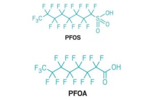
Perfluoroalkyl and Polyfluoroalkyl Substances (PFAS) chemicals are often referred to as “forever chemicals” as they do not naturally degrade. They have contaminated some water supplies causing adverse health impacts ranging from cancer to liver disease and fertility disruption.
PFAS chemicals are detected in wastewaters and landfill leachate due to their widespread uses in consumer and industrial products.
There are three existing options for removing PFAS from wastewaters: granular activated carbon (GAC), ion-exchange (IX) resins, and high-pressure membrane filtration of nanofiltration and reverse osmosis (RO). Treatment systems need to be engineered carefully with the consideration of specific wastewater chemistry, co-contaminant removals, and the pros and the cons of these treatment options.
The disposal of PFAS-contaminated GAC, IX resins or PFAS-concentrated brine may pose secondary risks and should be considered carefully.
New advances in desalination technologies can help reduce PFAS treatment and disposal costs.
PFAS the “Forever Chemicals”
Perfluoroalkyl and Polyfluoroalkyl Substances (PFAS) are a group of man-made carbon-fluorine chemicals that have been produced since the 1940s. They were widely used in non-stick household products, stain-repellants, food paper packaging (e.g., compostable coffee cups and pizza boxes), lubricants, aviation firefighting foams, and many more. PFAS are comprised of a water-liking “head” group (making them soluble in water) and a long perfluoroalkyl or polyfluoroalkyl “tail” group that is made up of carbon-fluorine bonds.
The carbon-fluorine bond is one of the strongest chemical bonds, which results in PFAS chemicals not degrading easily. As such, PFAS are often called “forever chemicals”. PFAS have been found in surface water, groundwater, drinking water sources, wastewater treatment plant effluent and landfill leachates. People may be exposed to PFAS by consuming PFAS-contaminated water or food. PFAS can be harmful to human health, causing cancer, liver damage, and a depressed immune system among other impacts. The U.S. EPA is taking action by proposing regulations to protect drinking water and to clean up PFAS-contaminated water sources.
Existing Treatment Options for PFAS Contaminated Waters
Treating PFAS contaminated water before discharge to aquatic receiving sources will reduce its accumulation in water systems. Currently, industrialized methods for removing PFAS from contaminated waters are based on (1) physical adsorption technologies, such as granular activated carbon (GAC) and ion-exchange (IX) resins; and (2) high-pressure membrane filtrations, such as nanofiltration (NF) or reverse osmosis (RO). Although work is being done on advanced oxidation techniques, these are not yet commercial and could come with a very high energy demand.
The selection of an appropriate treatment method requires careful considerations based on the specific water chemistry, contaminant removals and the required quality of the treated water. In industrial wastewater treatment, the water composition is more complex than that of “clean” drinking water and includes co-contaminants besides PFAS. The presence of co-contaminants will impact the selection of a method, the treatment system sizing and the eventual costs. For example, landfill leachate has co-contaminants of organics, inorganics and volatiles, in requiring removal in addition to PFAS and to varying degrees.
The pros and cons for the three industrialized PFAS removal methods are summarized in the below table.
Granular activated carbon (GAC)
Pros
• Reduce PFAS to ng/L level for drinking water.
• Effective for long-chain PFAS removal.
Cons
• Quick PFAS (short-chain PFAS in particular) breakthrough and frequent filter replacement due to weak interactions between PFAS and carbon.
• Not cost effective for waters containing other organic compounds since GAC is non-selective and will be over-loaded by other organics.
• Does not remove inorganics.
• GAC is a very expensive consumable. It can be manual intensive GAC to replace, or energy intensive regeneration (often off-site via extreme temperature vaporization).
Ion-exchange resin
Pros
• Effective for anionic and long-chain PFAS removal to ng/L level.
• Higher adsorption capacity and significantly faster reaction kinetics compared to GAC.
Cons
• Not effective for wastewater containing high levels of inorganic ions (i.e. TDS) and/or natural organic matter (NOM).
• Less affinity for short-chain PFAS.
• Incineration or regeneration of ion exchange resin required.
Nanofiltration or reverse osmosis
Pros
• Effective for both short-chain and long-chain PFAS.
• Capable of handling co-contaminants and treating all types of PFAS-contaminated water.
• High loading flow rate.
• Can be partnered with a disposal well (common in North America) to permanently dispose of the PFAS brine.
Cons
• Possible membrane fouling by scaling inorganic compounds.
• Concentrated brine management, which can be solved through high recovery performance to minimize brine produced and disposed (concentrate the PFAS to the maximum extent in ultra-high recovery RO while avoiding scaling of RO system).
A PFAS removal process may integrate multiple technologies, for example, an upstream reverse osmosis process with a high loading flow rate followed by a downstream GAC or IX-resin polishing step to meet stringent water quality requirements. Refer to our article for an overview of the importance of understanding the water chemistry, especially for nanofiltration and reverse osmosis processes. An experienced wastewater treatment team can engineer and price a solution including initial desk study for the PFAS-removal system, site investigations, and risk assessments.
Technologies to Permanently and Economically Treat PFAS Wastewater
Physical separation technologies (GAC, IX resin, NF, or RO) do not destroy PFAS but only remove PFAS from contaminated water onto adsorbents or into a concentrated brine. The disposal of PFAS-contaminated absorbents or PFAS-concentrated brine may pose secondary pollution risks. Technologies for permanently degrading PFAS are based on high-energy incineration or advanced oxidations including electrochemical oxidation, microwave thermal treatment, photolytic degradation, pyrolysis, and sonochemistry. These extreme PFAS degradation pathways are very costly, especially when treating large volumes and flow rates of PFAS wastewater. It is thus ideal to use other relatively cost-effective technologies to first reduce PFAS wastewater volume and concentrate PFAS into its highest allowable concentration together with co-contaminate removals. The highly concentrated PFAS wastewater can then be transported to either a disposal well for permanent disposal deep underground or a PFAS-specialized degradation site for final destruction.
PFAS destruction by any means will release fluorine atoms/fluoride ions. When incineration is used to destroy PFAS, fluorine may become airborne and require air scrubbing technology which may produce fluoride-rich wastewater. If using advanced oxidation instead, fluoride ions will be present in the treated water.
Saltworks is an established leader in delivering modular, automated fluoride removal plants, including to leaders in the semiconductor industry. As explained in our article on fluoride, reacting fluoride with calcium forms calcium fluoride, which is filtered out of the water as easy-to-dispose of compact solids and they can be implemented downstream of PFAS destruction.
New advances in desalination technologies (ultra-high pressure reverse osmosis, minimal liquid discharge (MLD) and zero liquid discharge (ZLD), such as our modular BrineRefine, XtremeRO, and our SaltMakerfamily of evaporator crystallizers) can help economically reduce PFAS wastewater volume and concentrate PFAS to a level that was previously unreachable. These modular mobile water treatment units can also be deployed to a PFAS wastewater site for onsite treatment. Our article on how to manage brine disposal & treatment provides a summary of management options.
Contact Saltworks for a detailed review of your PFAS project, risk and opportunities, as well as options to manage the result brine residuals.
About Saltworks
Saltworks Technologies is a leader in the development and delivery of solutions for industrial wastewater treatment and lithium refining. By working with customers to understand their unique challenges and focusing on continuous innovation, Saltworks’ solutions provide best-in-class performance and reliability. From its headquarters in Richmond, BC, Canada, Saltworks’ team designs, builds, and operates full-scale plants, and offers comprehensive onsite and offsite testing services with its fleet of mobile pilots.
Reverse osmosis (RO) is the best available technology to treat landfill leachate for surface discharge. Possible trace volatile organic compounds (VOCs) and ammonia emerging in the RO permeate can be removed with a polishing step to meet the highest discharge standards.
Saltworks has started commissioning what we believe is a first-of-its-kind plant, with much customer interest. The membrane concentrator makes extensive use of reverse osmosis – turbocharged.
Saltworks’ advanced technology treats PFAS wastewaters to each client’s specifications. Our solutions can integrate into existing or new wastewater processes.
Heavy industry, manufacturing, and natural resource-based industries often use large volumes of water and generate wastewaters requiring treatment. Saltworks designs, builds, and operates advanced wastewater treatment plants that economically and reliably treat tough industrial wastewaters.
Recent reverse osmosis (RO) improvements enable extreme recoveries of up to 99% in the treatment of cooling tower blowdown (CTB) for minimal liquid discharge (MLD) or reducing the cost of zero liquid discharge (ZLD) systems.
Ultra-high-pressure (UHP) spiral wound membrane systems can achieve brine concentrations of 130,000 mg/L total dissolved solids (TDS)—near those of evaporators—as long as scaling and fouling are controlled.
Each incremental treatment addition can improve volume reduction and recovery, but can increase costs and complexity.
Knowing your brine disposal costs allows you to determine where to stop in the treatment process.
Background
Cooling towers are used by industrial plants to eject waste heat to atmosphere. Evaporation of water removes heat and results in concentration of ions and metals in the cooling water that remains. A portion of the cooling water is blown down after a number of cycles, before the ions and metals reach their concentration scaling limits. This cooling tower blowdown (CTB) water requires management. Meanwhile, the water lost as blowdown or from evaporation or drift must be replaced with makeup water, typically from a freshwater source.
Once the CTB is generated, options for managing cooling tower blowdown (CTB) consist of:
Directly discharging to nearby surface water or land, if regulations permit
Storage and volume reduction in an evaporation pond, if climate and regulatory conditions are favorable
Disposal via injection wells, if located near the site
Discharge to a local wastewater treatment facility, if operators agree to accept it
Treatment of CTB for discharge or reuse
This article focuses on the last option: CTB treatment.
Important Cooling Tower Project Considerations
Before deciding how to manage CTB, key project information must be gathered first:
Water chemistry, flow rate, and scaling potential: Our article on RO & Evaporator Scale Control discusses how scale forms, its implications for water treatment systems, and how to avoid scaling. Alternatively, contact Saltworks and we can help you.
Required quality of treated water: Whether water is reused in the plant, reused elsewhere, or discharged, any water treatment system will need to meet the relevant water quality criteria.
Brine management options: CTB consists of inorganic constituents; industrial desalination technology used to treat the water will generally produce a concentrated brine. Our article on how to manage brine disposal & treatment describes several options.
Considering these details and any other important plant information will allow a critical assessment of options and their economics.
CTB Treatment Economics
Once the CTB has been generated, treatment solutions vary from relatively minor, targeted interventions, to comprehensive full treatment trains that combine membrane and thermal systems to achieve minimal liquid discharge (MLD) or zero liquid discharge (ZLD).
Understanding the cost of alternate (non-treatment) CTB management options is important for properly comparing total treatment costs and what treatment options are possible within a given budget. To keep these total costs low, it is usually beneficial to achieve the highest RO recovery possible, thus minimizing more expensive volume reduction further downstream in evaporators or offsite transport for disposal.
It should be noted that seemingly small changes in recovery percentages have a large, non-intuitive impact on brine volume. For example, boosting recovery from 95% to 97.5% may seem like gaining “only 2.5%”. However, this means halving the volume of the remaining brine and therefore 50% fewer trucks needed for disposal (or 50% smaller evaporation pond capacity or a 50% smaller downstream evaporator). Savings from boosting recovery can be enormous, as demonstrated in the CTB treatment case study below.
Pilot Case Study
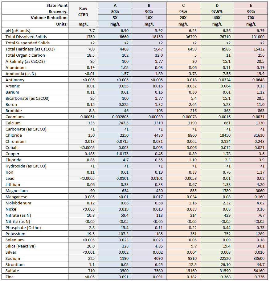
A North American power plant was sending their CTB to evaporation ponds. However, the ponds were reaching capacity and offsite disposal was an expensive option. The power plant sought a treatment option to reduce offsite disposal volumes in order to lower costs. The treated water needed to meet utility water reuse requirements such that TDS < 500 mg/L. The water chemistry is summarized in Table 1.
Table 1: Power Plant Water Chemistry: Raw, and at Each Successive Recovery Increase
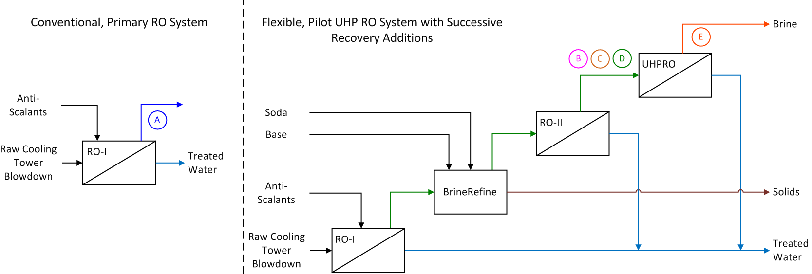
With a TDS of 1,750 mg/L, the raw CTB is suitable for treatment by reverse osmosis (RO). 80% recovery is achievable with a conventional, primary RO system, reducing CTB volume by 5x. After the primary RO, the volume can be further reduced and recovery increased using other technologies, including ultra-high pressure reverse osmosis. A flexible pilot system with multiple process configurations to analyze performance and cost at incrementally increasing recoveries was tested on the CTB.
Figure 1 shows a simplified process flow diagram of the pilot system. The incremental process steps and their costs are explored below for volume reductions (and recoveries) of 10x (90%), 20x (95%), 40x (97.5%), and 70x (99%). Brine concentration and composition changes with each incremental step in recovery improvement are shown in Table 1. Table 2 shows the recovery at each stage, the volume reduction, the technology to achieve it, and the cost guidance.
Figure 1: Process Flow Diagram (PFD) Showing Successive Recovery Additions
RO-I with anti-scalants, concentration polarization management, and flushes
$1–2 /m3
B
10X
90%
Above + high pH, UF & RO-II
$2–3 /m3
C
20X
95%
Above + some soda ash
$3–3.5 /m3
D
40X
97.5%
Above + more soda ash
$3.5–5.8 /m3
E
70X
99%
Above + UHP-RO
$4–8 /m3
Pilot Results and Knowing What Recovery to Target and When to Stop
This pilot study and others like it provide cost and performance data for a broad range of process configurations and recoveries. Varying the quantity of soda ash (sodium bicarbonate) alone provided a lot of flexibility in achieving the desired recovery. It is generally advisable to stay below 80% calcium sulfate saturation in the brine to prevent irreversible scaling. Adding soda ash can increase recovery but is typically a costly approach and should therefore be controlled carefully. Saltworks has technologies available to help with keeping chemical consumption costs down.
Besides flexibility with process steps, the proper integration of pilot plant elements is also important for this kind of study. Although each step can be viewed as a unit operation, properly assessing the performance of a treatment chain requires considering an integrated plant with unified process controls. This is recommended for the following critical reasons:
As feedwater chemistry and flow rates change upstream, an integrated plant better reacts and adjusts each unit operation accordingly, for example by using real-time sensors and controls to adjust chemical dosing.
Performance monitoring algorithms can be applied. This is done at both the plant and unit operation level, whereby upstream and downstream systems communicate their performance and status to one another. Adjustments can then be made to achieve the best overall system efficiency. A unified dashboard helps plant operators and owners to monitor performance.
Cohesion of process control design methods, control system components, and documentation for both capital cost and operational cost efficiency (e.g. spares and maintenance) can be ensured.
Economic Guidance
Readers are offered the following reminders and guidance when considering CTB and brine treatment economics:
Sum the costs of chemical treatment and secondary RO, since the secondary RO requires chemical treatment. For example, the net cost of a secondary RO may be $8/m3 ($4/m3 chemical treatment + $4/m3 RO).
Thermal system costs are typically >$20/m3, so although the advanced membrane brine system costs may seem high compared to potable water RO, these costs are still much lower than thermal brine concentration.
Know where to stop: For example, if a brine disposal outlet is available for $5/m3, a primary RO system may offer economic advantages for concentrating brine, while a secondary RO may not.
Capacity matters: For smaller capacity plants, adding unit operations adds process and operational complexities. For example, if the brine flow rate from the primary RO is 100 m3/day and a thermal system is economic (e.g. disposal costs >$10/m3), it may make more sense to skip the secondary RO and proceed directly to the thermal system. This is especially true if chemical treatment is avoided by using a SaltMaker evaporator crystallizer that does not require upstream pre-treatment. At higher brine flow rates, such as 500 m3/day, a secondary membrane concentrator can be highly cost advantageous.
Simple bench or pilot tests considerably de-risk investments and offer pay back periods of weeks to months by enabling economic and process optimization of the overall system.
Project owners do not need to become experts in advanced brine treatment or economic optimization. Contact Saltworks for help and guidance on completing these calculations.
About Saltworks
Saltworks Technologies is a leader in the development and delivery of solutions for industrial wastewater treatment and lithium refining. By working with customers to understand their unique challenges and focusing on continuous innovation, Saltworks’ solutions provide best-in-class performance and reliability. From its headquarters in Richmond, BC, Canada, Saltworks’ team designs, builds, and operates full-scale plants, and offers comprehensive onsite and offsite testing services with its fleet of mobile pilots.
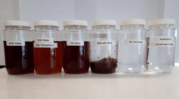
Saltworks Technologies Inc. (Saltworks) completed an end-to-end zero liquid discharge (ZLD) and zero air emission off-site pilot to treat concentrated reverse osmosis leachate brine from a municipal landfill in China.
The site presently treats raw leachate with biological treatment, conventional RO, and disc tube RO (DTRO) systems. The DTRO brine reject is sent back to the landfill. However, the TDS of leachate is getting higher. The client is preparing for new regulations that could forbid this practice. The project objective was therefore to eliminate the wastewater volume by producing both clean water and solids at the lowest total cost of ownership.
For the complete results of the pilot, including detailed water chemistry, download the free case study below.
Download the free Landfill Wastewater Pilot results
Saltworks Technologies is a leader in the development and delivery of solutions for industrial wastewater treatment and lithium refining. By working with customers to understand their unique challenges and focusing on continuous innovation, Saltworks’ solutions provide best-in-class performance and reliability. From its headquarters in Richmond, BC, Canada, Saltworks’ team designs, builds, and operates full-scale plants, and offers comprehensive onsite and offsite testing services with its fleet of mobile pilots.