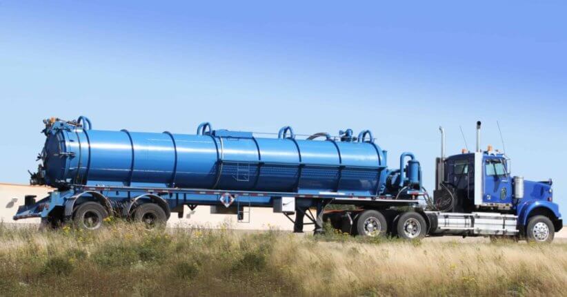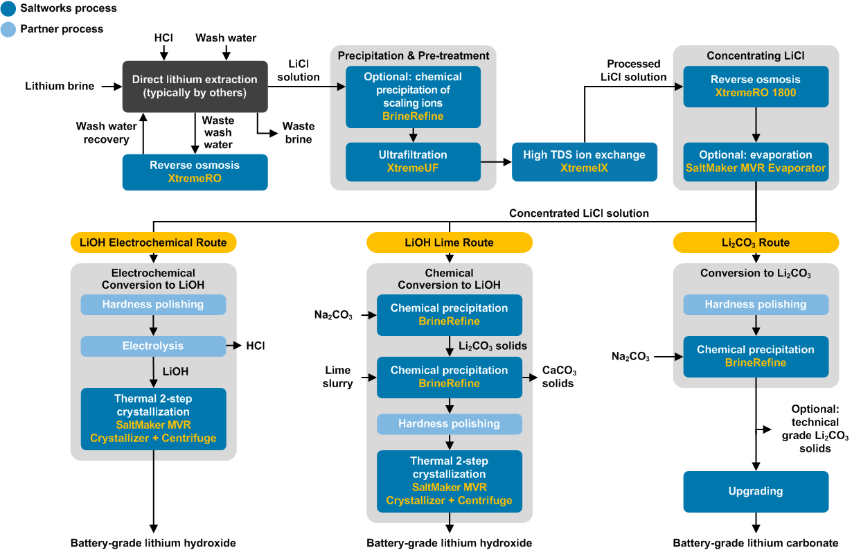
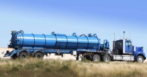
How to Manage Brine Disposal & Treatment
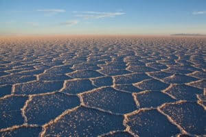
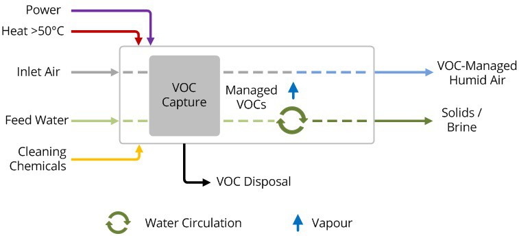
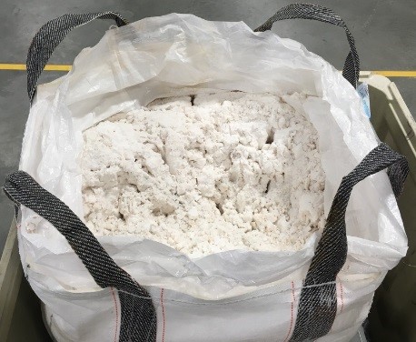
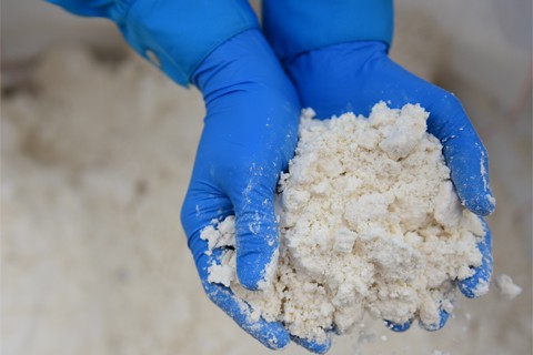
The many options for managing brine, a term for saline wastewater from industrial processes, fall under two categories: brine treatment and brine disposal. Brine treatment involves desalinating the brine for reuse and producing a concentrated brine (lower liquid waste volume), or residual solids (zero liquid discharge).

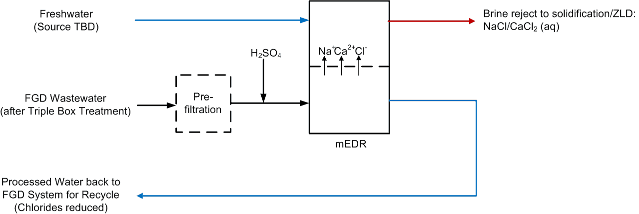
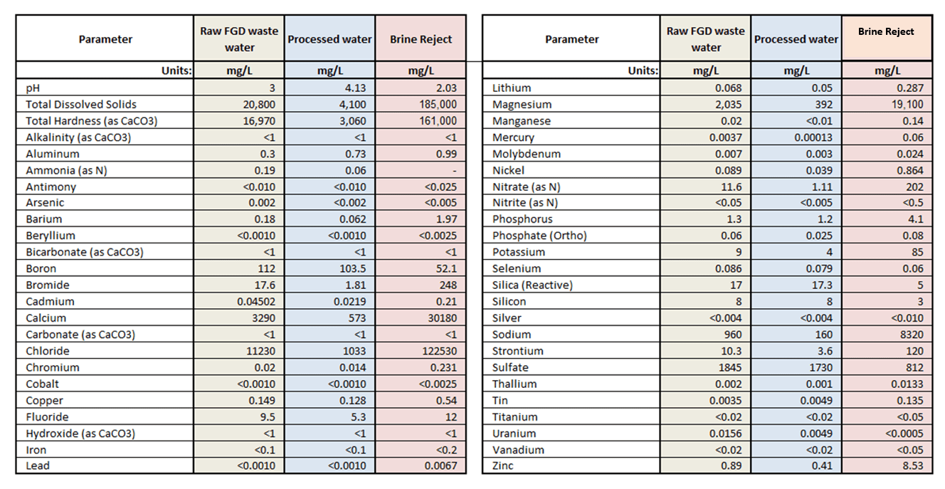
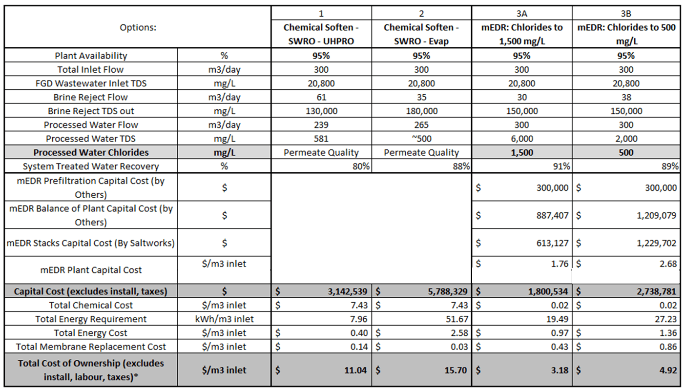
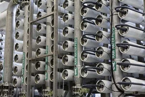
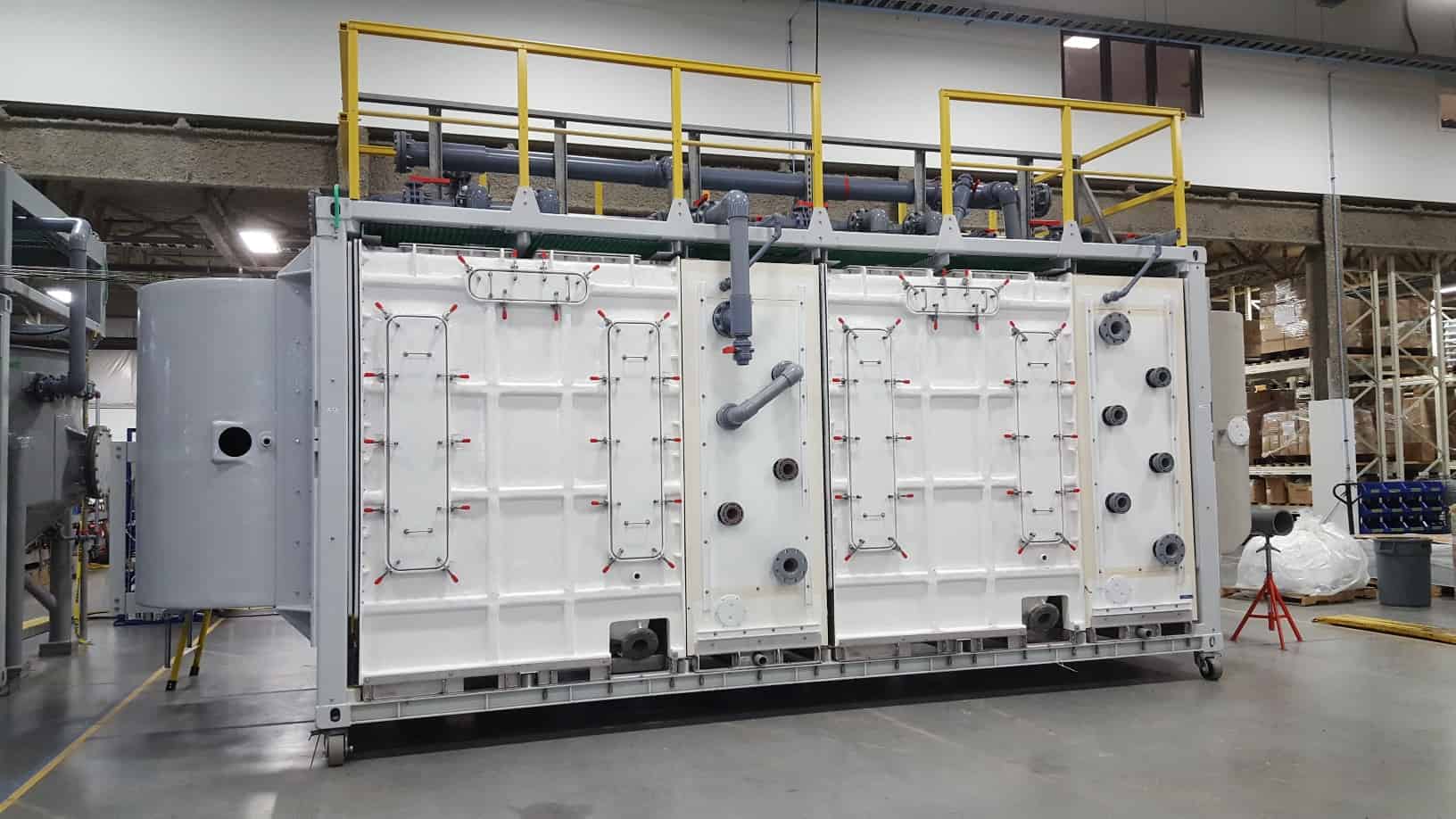
How to Improve FGD Economics with Chloride Removal using Selective EDR
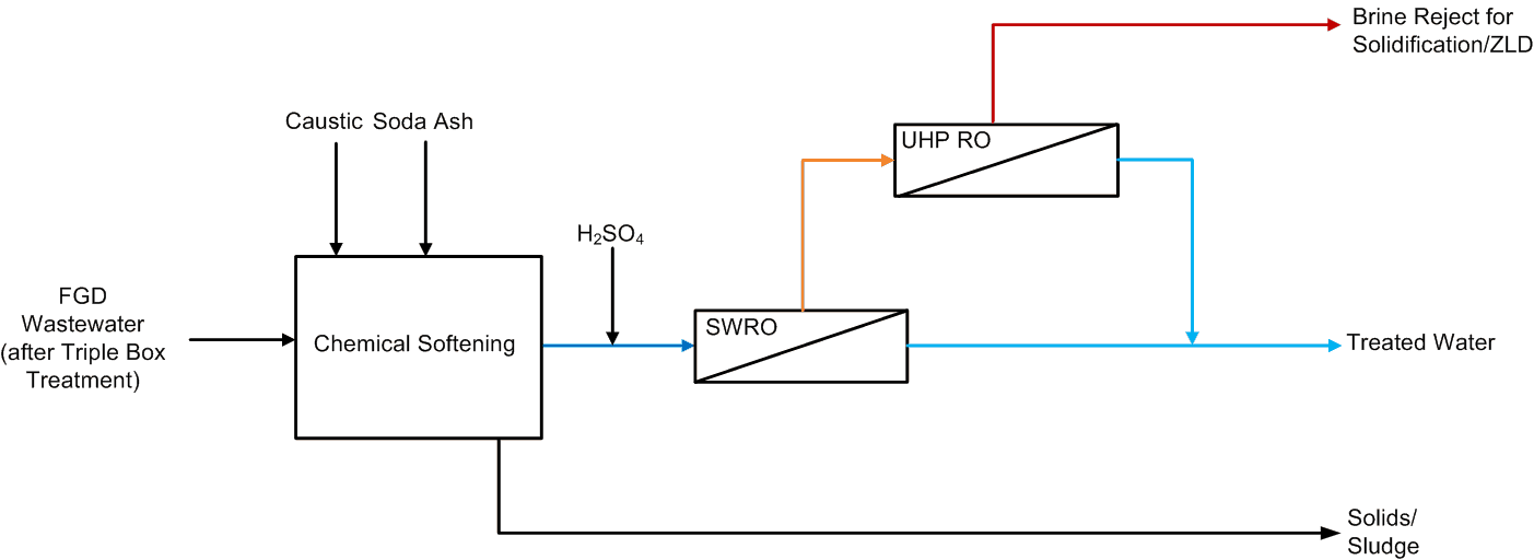
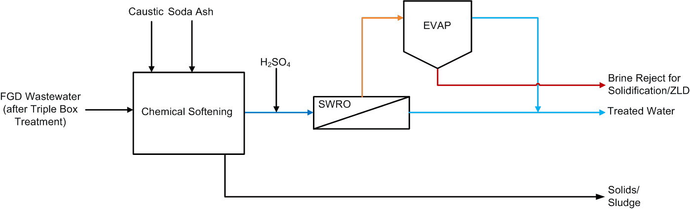
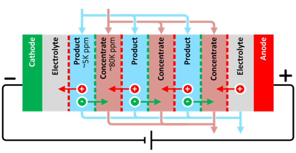
As regulations on FGD wastewater tighten, additional treatment is required. Often, this is chemically intense, and high cost. The best means to lower treatment costs is to reduce the volume of wastewater generated, usually by increasing internal recycle.
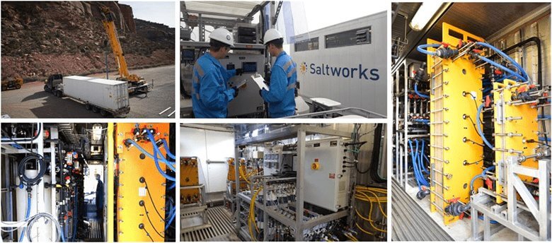
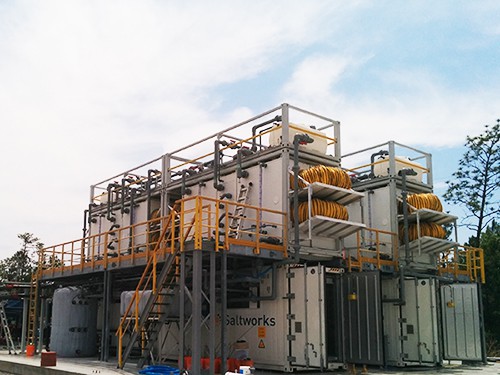
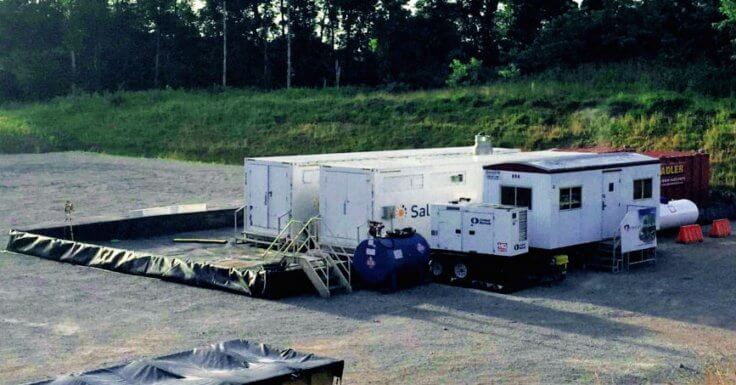
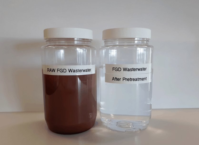
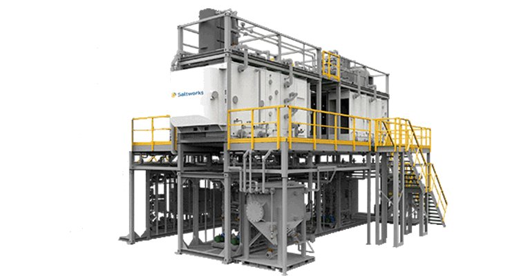
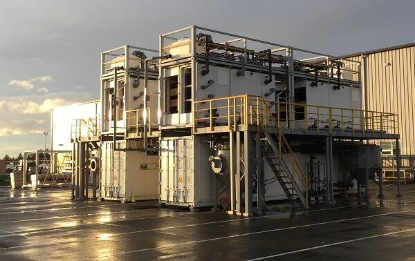
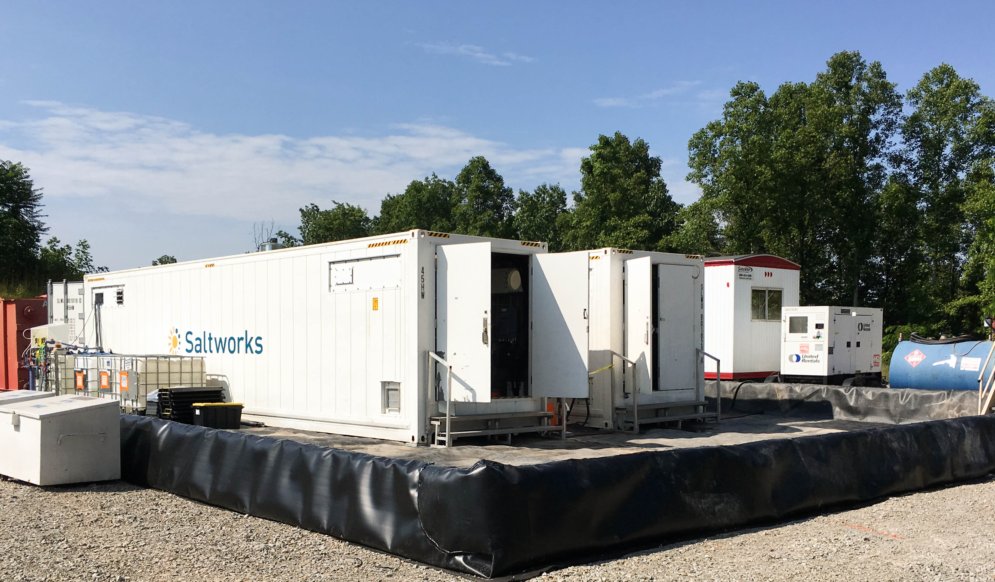
First-of-Its-Kind Coal FGD Wastewater Treatment Pilot Deployed
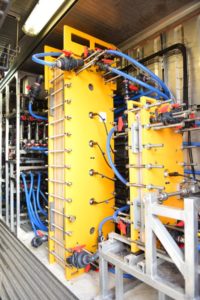
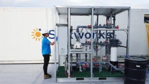
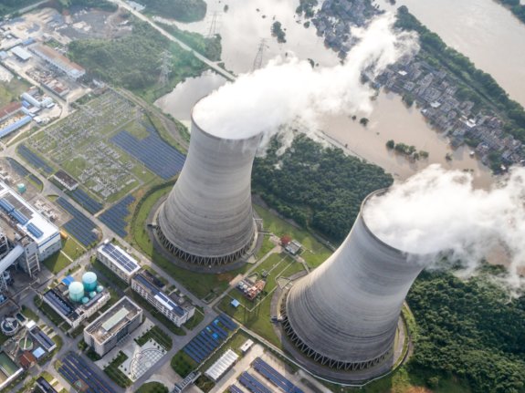
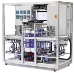
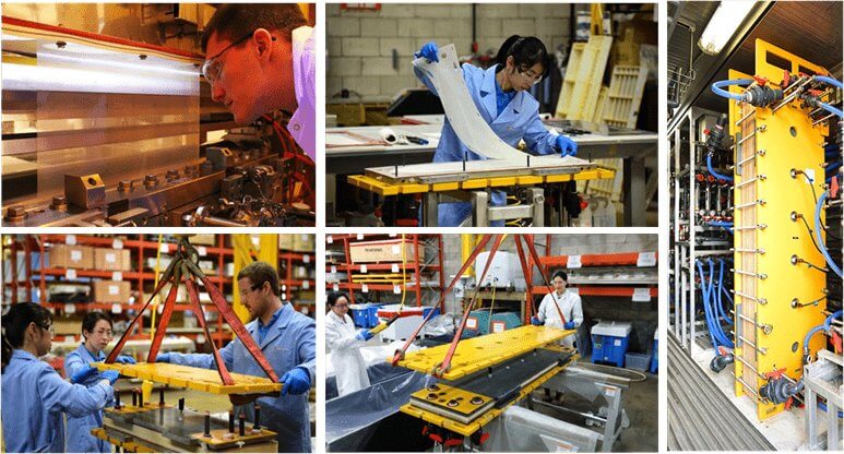
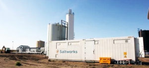
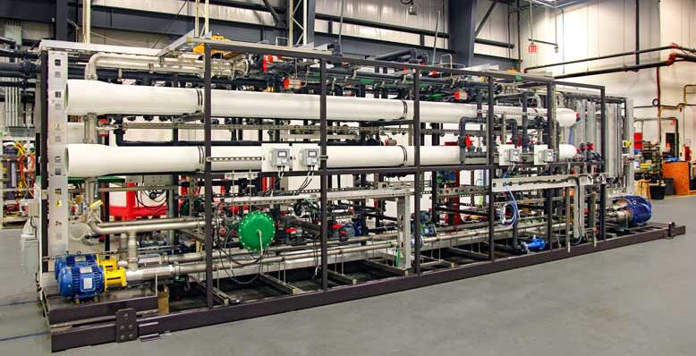
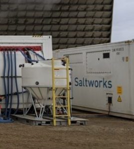
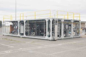
Saltworks has shipped a novel FlexEDR system to the southern United States that will clean up coal fired power wastewater. Flue gas desulfurization (FGD) wastewater is a byproduct of sulfur scrubbers, installed to prevent acid rain from coal plants.
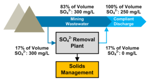
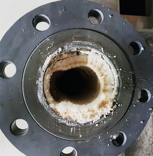
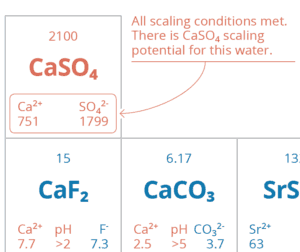
Sulfate Discharge: Measurement and Cost-Optimized Removal
There are many sulfate treatments available, with different advantages and disadvantages. Factors for consideration include capital and operational costs, solid vs. liquid brine reject for disposal, if the need is seasonal or year-round, and suitability for adverse operating conditions.


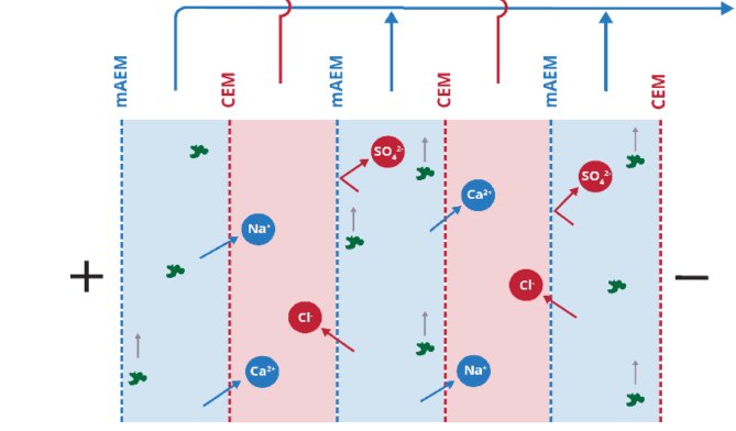

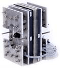
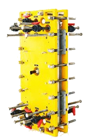
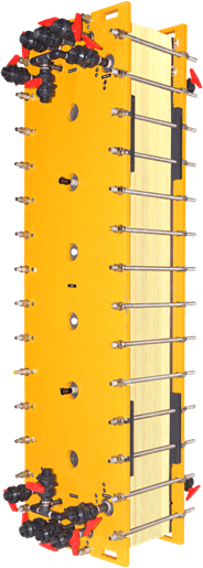
 using selective membranes and FlexEDR technology")